Preface
I switched my sump pump from a column to a submersible pump type. The change also included covering over and sealing access to the sump pit. Now my dilemma is how do I know if the pump fails and the sump pit fills with water? I don’t want to come down to the basement someday and find water pooling on the floor. With an inexpensive sensor, some microelectronics and an integration with Home Assistant, I have a system to notify me of a pump failure before the sump pit overflows.
Moisture Sensor
At the heart of the solution is a capacitive moisture sensor like this one.

I mounted in on a PCV pipe so that the sensor can sit in the corner of the sump pit.


System Requirements
I had a few requirements for the monitoring and reporting solution.
I don’t want to rely on checking the sump level status at the sump pit: I don’t visit this area of the basement very often. It’s in a crawl space away from living areas.
I want an audible alarm when the system detects that the pit has a higher-than-expected water level.
I want to be able to test the sensor periodically.
When I test the sensor, I want to test the detection and reporting system too, not just the moisture sensor.
System Components
Two ESP32 microprocessors serve as the platforms for the sump pit sensor and the alarm. A Raspberry Pi running the Home Assistant operating system coordinates communication between the ESP32s. Both run REST servers. Home Assistant periodically queries the sump pit REST server to determine the state of the capacitive moisture sensor. HA updates a card on the dashboard with the state. When the sensor is wet, HA makes a call to a REST endpoint on the ESP32 alarm to turn on a buzzer and light.

Sump Pit Sensor
The following diagram shows the breadboard configuration of the sump pit sensor.

Two LEDs show the status of the sump pit. The green LED indicates that the water level is below the capacitive moisture sensor. The RED LED lights when the sensor is wet. A toggle switch provides a means to test the sensor. In test mode, the GPIO pin assigned to the capacitive sensor is grounded, leading to a fault state.
The ESP32 sketch relies on the WiFi manager to obtain network credentials; I don’t need to hardcode the SSID or password. To allow for a one-time setup – and for a network change should one day I change IP providers – I have a switch to reset the access point. When the access point GPIO pin is high, the sketch resets network settings previously obtained and stored in the ESP32.
Alarm
The alarm configuration resembles the following diagram.

A solid-state relay turns on a buzzer and light under an alarm condition. I used a 12-volt car part for the buzzer/light combination. The reset access point switch in this configuration is identical to that for the sump pit sensor. The alarm includes a 128 x 32 OLED display so that I can see an alarm code if activated. This code gives me flexibility to add other alarm conditions into Home Assistant in future. A pushbutton lets me silence the buzzer but leave the alarm code displayed. I reset the alarm code — currently — with a curl command from my computer.
Home Assistant
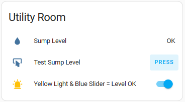
I created a card on the dashboard to represent the state of the sump pit sensor.

A button gives me the ability to test the sensor. If everything is working as expected, pressing the button turns the lamp icon yellow and moves the slider to the right.
The HA card configuration is relatively simple.
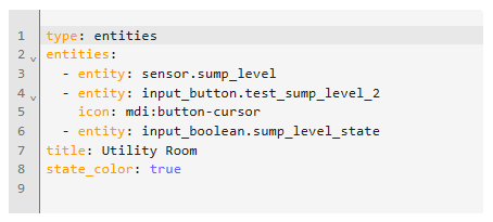
The additional lines for the /homeassistant/configuration.yaml file are as follows.
command_line:
  - sensor:
      command: "curl http://192.168.2.110:5000/getValue --header Content-Type:application/json"
      name: "Sump Level"
      unique_id: sump_level
      value_template: '{{ value_json.Level }}'
      scan_interval: 60

shell_command:
  test_sump_level: curl http://192.168.2.110:5000/test --header Content-Type:application/json
  turn_off_alarm: curl http://192.168.2.117:5000/turnOffAlarm
  turn_on_alarm: curl -X POST http://192.168.2.117:5000/turnOnAlarm -H "Content-Type:application/json" -d '{"alarmId":"101"}'
The /homeassistant/automations.yaml entry for testing the sump level is as follows.
- id: '1744807953733'
  alias: Test sump level sensor
  description: Send a REST call to get the status of the sump level sensor
  triggers:
  - trigger: state
    entity_id:
    - input_button.test_sump_level_2
  conditions: []
  actions:
  - action: system_log.write
    metadata: {}
    data:
      level: warning
      message: Sump level tested by pressing button on dashboard
      logger: Sump
  - action: shell_command.test_sump_level
    metadata: {}
    data: {}
    response_variable: test_response
  - if:
    - condition: template
      value_template: '{{ test_response[''stdout''] != ''{"Sensor":"Sump Level","Level":"OK"}''}}'
    then:
    - action: shell_command.turn_on_alarm
      data: {}
    - action: system_log.write
      metadata: {}
      data:
        level: error
        message: Sump pump is NOT running {{ test_response['stdout'] }}
    - if:
      - condition: state
        entity_id: input_boolean.sump_level_state
        state: 'on'
      then:
      - action: input_boolean.turn_off
        metadata: {}
        data: {}
        target:
          entity_id: input_boolean.sump_level_state
    else:
    - action: system_log.write
      metadata: {}
      data:
        level: warning
        message: Sump level is OK
    - choose:
      - conditions:
        - condition: state
          entity_id: input_boolean.sump_level_state
          state: 'off'
        sequence:
        - action: input_boolean.turn_on
          metadata: {}
          data: {}
          target:
            entity_id: input_boolean.sump_level_state
  mode: single
Alarm Automations
I need two automations for the alarm: one to turn the alarm on and another to turn it off. Here are the automations.yaml entries for each.
- id: '1747480539007'
  alias: Sump pit full alarm on
  description: ''
  triggers:
  - trigger: state
    entity_id:
    - sensor.sump_level
    from: OK
    to: FULL
  conditions: []
  actions:
  - action: shell_command.turn_on_alarm
    metadata: {}
    data: {}
  mode: single
- id: '1747480803087'
  alias: Sump pit okay alarm off
  description: ''
  triggers:
  - trigger: state
    entity_id:
    - sensor.sump_level
    from: FULL
    to: OK
  conditions: []
  actions:
  - action: shell_command.turn_off_alarm
    metadata: {}
    data: {}
  mode: single
To add these automations with settings/automations & scenes, click on the + CREATE AUTOMATION button on the bottom right corner of the dashboard. Select Create new automation from the menu that appears. Click on + ADD TRIGGER and then Entity and State. In the Entity* window, type sump level and press return to select this entity. In the From (optional) window type OK. In the To (optional) window type FULL. Scroll down to Then do and press + ADD ACTION. In the Search action window, type Shell Command and select the entry for turn_on_alarm. Click SAVE in the bottom right corner. In the Name* window, name the automation Sump pit full alarm on and click SAVE.
Follow similar steps to add the alarm off automation.
Sump Sensor Sketch
Here’s the code for the sump pit sensor.
#include "Arduino.h" #include "WebServer.h" #include "ArduinoJson.h" #include "WiFiManager.h #include "esp_mac.h" #include "esp_wifi.h" // sensor in air: analog value around 3090 // sensor in 2cm of water: analog value around 2000 // sensor in water to white line: analog value around 1360 #define DRY_LIMIT 2000 #define SENSOR_KEY "Sensor" #define SENSOR_VALUE "Sump Level" #define LEVEL_KEY "Level" #define LEVEL_VALUE_GOOD "OK" #define LEVEL_VALUE_BAD "FULL" #define GET_VALUE_ENDPOINT "/getValue" #define TEST_ENDPOINT "/test" #define BUFFER_LEN 1024 #define TURNED_OFF 0 #define TURNED_ON 255 #define SERVER_PORT 5000 WebServer server(SERVER_PORT); const int moisturePin = 36; // The analog pin connected to the sensor const int resetCreds = 34; const int turnOffAlarm = 18; const int redLED = 12; const int greenLED = 14; StaticJsonDocumentjsonDocument; char buffer[BUFFER_LEN]; unsigned long button_time = 0; unsigned long last_button_time = 0; void getValue() { jsonDocument.clear(); // Clear json buffer jsonDocument[SENSOR_KEY] = SENSOR_VALUE; int moistureValue = analogRead(moisturePin); // Read the analog value if (moistureValue < DRY_LIMIT) { jsonDocument[LEVEL_KEY] = LEVEL_VALUE_BAD; analogWrite(greenLED, TURNED_OFF); analogWrite(redLED, TURNED_ON); } else { jsonDocument[LEVEL_KEY] = LEVEL_VALUE_GOOD; analogWrite(greenLED, TURNED_ON); analogWrite(redLED, TURNED_OFF); } serializeJson(jsonDocument, buffer); server.send(200, "application/json", buffer); } void setupApi() { server.on(GET_VALUE_ENDPOINT, getValue); server.on(TEST_ENDPOINT, getValue); // start server server.begin(); } void IRAM_ATTR isr() { button_time = millis(); if (button_time - last_button_time > 250) { last_button_time = button_time; } } void setup() { // put your setup code here, to run once: Serial.begin(115200); // This delay gives the chance to wait for a Serial Monitor without blocking if none is found delay(1500); Serial.println("Setting up ..."); delay(5000); pinMode(moisturePin, INPUT); pinMode(resetCreds, INPUT); pinMode(redLED, OUTPUT); analogWrite(redLED, 0); pinMode(greenLED, OUTPUT); analogWrite(greenLED, 255); WiFi.mode(WIFI_STA); // explicitly set mode, esp defaults to STA+AP WiFi.STA.begin(); // Force use of the fused MAC address so we can set a static IP on the router uint8_t baseMac[6]; esp_err_t ret = esp_wifi_get_mac(WIFI_IF_STA, baseMac); Serial.printf("%02x:%02x:%02x:%02x:%02x:%02x\n", baseMac[0], baseMac[1], baseMac[2], baseMac[3], baseMac[4], baseMac[5]); if (ret != ESP_OK) { Serial.println("ERROR: failed to set base MAC address, halting ..."); for(;;); } WiFiManager wm; if (digitalRead(resetCreds) == HIGH) { // reset settings - wipe stored credentials that are stored by the ESP library wm.resetSettings(); } bool res; Serial.println("auto connecting ..."); res = wm.autoConnect("AutoConnectAP"); // anonymous ap if(!res) { Serial.println("ERROR: failed to connect, restarting ..."); ESP.restart(); } else { Serial.println("Connected ..."); } // add a button to turn off the alarm pinMode(turnOffAlarm, INPUT_PULLUP); attachInterrupt(turnOffAlarm, isr, FALLING); setupApi(); } void loop() { // run repeatedly: server.handleClient(); }
Alarm Sketch
Here’s the sketch for the alarm component.
#include "Arduino.h"
#include "WebServer.h"
#include "ArduinoJson.h"
#include "WiFiManager.h"
#include "SPI.h"
#include "Wire.h"
#include "Adafruit_GFX.h"
#include "Adafruit_SSD1306.h"
#include "esp_mac.h"

#define SCREEN_WIDTH 128 // OLED display width, in pixels
#define SCREEN_HEIGHT 32 // OLED display height, in pixels
#define TEXT_SIZE 5      // largest text possible
#define ACTION_KEY "ACTION"
#define ACTION_RESPONSE "OK"
#define ERROR_RESPONSE "ERROR"
#define NO_DATA "ERR1"
#define OLED_RESET     4 // Reset pin # (or -1 if sharing Arduino reset pin)
#define SCREEN_ADDRESS 0x3C ///< See datasheet for Address; 0x3D for 128x64, 0x3C for 128x32
Adafruit_SSD1306 display(SCREEN_WIDTH, SCREEN_HEIGHT, &Wire, OLED_RESET);

// Web server running on port 5000
WebServer server(5000);
const int relay = 26;
const int resetCreds = 34;
const int silenceAlarm = 18;
unsigned long button_time = 0;
unsigned long last_button_time = 0;
StaticJsonDocument<1024> jsonDocument;

char buffer[1024];

void displayText(const char *text)
{
  /* display up to four characters ... any more than that won't fit */
  display.clearDisplay();
  display.setTextSize(TEXT_SIZE);             // pixel scale
  display.setTextColor(SSD1306_WHITE);// draw white text
  display.setCursor(0,0);             // Start at top-left corner
  display.println(F(text));
  display.display();
}

void formatOkJson() {
  jsonDocument.clear(); // Clear json buffer
  jsonDocument[ACTION_KEY] = ACTION_RESPONSE;
  serializeJson(jsonDocument, buffer);
}

void formatErrorJson() {
  jsonDocument.clear(); // Clear json buffer
  jsonDocument[ACTION_KEY] = ERROR_RESPONSE;
  serializeJson(jsonDocument, buffer);
}

void turnOnAlarm() {
  Serial.println("Turning on alarm ...");
  String body = server.arg("plain");
  int responseCode = 200;
  deserializeJson(jsonDocument, body);
  const char* alarmId = jsonDocument["alarmId"];
  if (alarmId == nullptr) {
    displayText(NO_DATA);
    formatErrorJson();
    responseCode = 400;
  } else {
   digitalWrite(relay, HIGH);
   displayText(alarmId);
   formatOkJson();
  }
  server.send(responseCode, "application/json", buffer);
}

void turnOffAlarm() {
  Serial.println("Turning off alarm ...");
  digitalWrite(relay, LOW);
  displayText(ACTION_RESPONSE);
  formatOkJson();
  server.send(200, "application/json", buffer);
}

void setupApi() {
  server.on("/turnOnAlarm", turnOnAlarm);
  server.on("/turnOffAlarm", turnOffAlarm);

  // start server
  server.begin();
}

void IRAM_ATTR isr() {
  button_time = millis();
  if (button_time - last_button_time > 250)
  {
    last_button_time = button_time;
    digitalWrite(relay, LOW);
  }
}

void setup() {
  Serial.begin(115200);
  // This delay gives the chance to wait for a Serial Monitor without blocking if none is found
  delay(1500);

  if(!display.begin(SSD1306_SWITCHCAPVCC, SCREEN_ADDRESS)) {
    Serial.println(F("ERROR: SSD1306 allocation failed, halting ..."));
    for(;;);
  }
  delay(2000);
  displayText("");

  pinMode(relay, OUTPUT);
  pinMode(resetCreds, INPUT);

  pinMode(silenceAlarm, INPUT_PULLUP);
  attachInterrupt(silenceAlarm, isr, FALLING);

  // Force use of the fused MAC address so we can set a static IP on the router
  // Why does this variable need to be set when the function call is going to force the use of the base MAC address?
  uint8_t baseMac[6] = {0x00, 0x00, 0x00, 0x00, 0x00, 0x00};
  esp_err_t ret = esp_base_mac_addr_set(baseMac);
  if (ret != ESP_OK) {
    Serial.println("ERROR: failed to set base MAC address, halting ...");
    for(;;);
  }

  WiFi.mode(WIFI_STA); // explicitly set mode, esp defaults to STA+AP
  WiFiManager wm;

  if (digitalRead(resetCreds) == HIGH) {
    // reset settings - wipe stored credentials that are stored by the ESP library
    wm.resetSettings();
  }

  bool res;
  res = wm.autoConnect("AutoConnectAP"); // anonymous ap
  if (!res) {
      Serial.println("ERROR: failed to connect, restarting ...");
      ESP.restart();
  }
  else {
      Serial.println("Connected ...");
  }
  setupApi();
}

void loop() {
  // run repeatedly:
  server.handleClient();


}
Testing the System
In the following video you can see me test the sensor system.